
What One of North America’s First Biocarbon Plants Taught NESTEC About Emissions Control
Biocarbon has moved from pilot projects to serious commercial-scale decarbonization, and steel is leading the way.
In October 2025, Steel Dynamics (one of North America’s largest steel producers and metal recyclers) launched BIOEDGE™, a lower-embodied-carbon steel product line that replaces anthracite with renewable biocarbon in its electric arc furnaces. That biocarbon comes exclusively from SDI Biocarbon Solutions, a Steel Dynamics–Aymium joint venture in Columbus, Mississippi, with an expected annual capacity of 228,000 metric tons. It is one of the largest renewable biocarbon production facilities in the world. Steel may be a major driver in decarbonization, but cement, agriculture, and specialty carbon markets are close behind.
NESTEC engineered and supplied the Wet Electrostatic Precipitator (WESP) system that treats that facility’s biocarbon process off-gas. It was one of North America’s first large-scale biocarbon installations, and NESTEC was engaged from the project’s earliest stages — before there was any established design playbook for this process. Every ton of biocarbon leaving Columbus for an electric arc furnace is controlled through emissions systems NESTEC engineered.
That project taught NESTEC something every biomass producer considering the move into biocarbon or biochar needs to hear: the exhaust from a pyrolysis reactor cannot be engineered like exhaust from a conventional biomass combustion system.
Pyrolysis Gas Doesn’t Stabilize
The common assumption in biocarbon production is that the reactor is the engineering challenge. Reactor temperature profiles, residence time, feedstock prep, and carbon yield certainly drive product quality and plant economics. But from an emissions standpoint, the harder problem often starts when process gas leaves the reactor. That’s when it begins changing.
Combustion gases generally stabilize as they cool. Pyrolysis-derived gases generally don’t. Heavy organic compounds that are vapors at reactor outlet temperatures start condensing into microscopic liquid droplets as the stream cools. Those droplets first hang in the gas as fine aerosols. With more cooling and residence time, they collide, grow, and eventually deposit on duct walls, dampers, fan blades, and heat-transfer surfaces.
At that point, the exhaust stops behaving like a flue gas and starts behaving like a multiphase process fluid:
- Fine particulates get coated with condensable organics.
- Liquid aerosols carry submicron particles.
- Shifts in moisture content change electrical conductivity, collection efficiency, and gas density.
The practical consequence is that you cannot select emissions control equipment from a pollutant concentration number on a process flow diagram. You have to engineer around the evolving physical behavior of the stream itself.
You Can’t Prevent Condensation. You Can Control Where It Happens.
Once you accept that the gas keeps evolving downstream, gas conditioning stops being a preparatory step and becomes a core process design decision.
In most industrial applications, conditioning is simple: cool the gas ahead of a scrubber, and add moisture before a precipitator. Biocarbon systems, however, demand more. Gas conditioning actively determines where condensation begins, how aerosols form, whether tar stays suspended or plates out on equipment, and ultimately how reliable the emissions system will be over years of operation.
The engineering objective is not to prevent condensation. Under most operating conditions, that’s impractical. The objective is to decide where condensation occurs and make sure it happens under controlled conditions, inside equipment built to manage it. That’s what a properly engineered quench section does: instead of letting the gas cool unpredictably across long duct runs, it establishes target temperature and moisture conditions within a defined portion of the process.
Optimal quench design depends on adequate residence time to let the stream approach thermal and chemical equilibrium before it reaches the collector. Uniform flow distribution matters more than intuition might suggest because high-velocity regions cut collection efficiency, while stagnant zones invite localized condensation and fouling. Temperature, moisture, velocity profile, and residence time are inseparable. Optimize one and neglect the others, and you rarely get the outcome you wanted.
When the Physics Changes, the Technology Has to Change
The biomass industry built its emissions toolkit of cyclones, multi-clones, fabric filters, scrubbers, and thermal oxidizers around relatively predictable combustion exhaust. Biocarbon changes that assumption. By the time gas leaves a thermal conversion reactor, it carries an evolving mix of condensable organics, liquid aerosols, moisture, and fine particulate.
This is where Wet Electrostatic Precipitators are helpful. A WESP operates on a fundamentally different collection mechanism than dry media. Instead of relying on inertia, filtration, or impaction, it imparts an electrical charge to suspended particles and liquid aerosols, which migrate to grounded collection surfaces that are continuously washed by a flowing water film. In a dry ESP or fabric filter, collected material sits in the equipment until it’s periodically removed. When the stream is loaded with sticky, condensable organics, that difference is critical.
WESP technology is also particularly effective on the submicron liquid aerosols that dominate portions of biocarbon exhaust, and at removing condensable material before it reaches thermal oxidizers, heat exchangers, or induced-draft fans downstream. That protects stack emissions numbers, reduces fouling potential, and improves equipment availability across the entire process train.
Proof in the Field: The SDI Biocarbon Solutions Installation
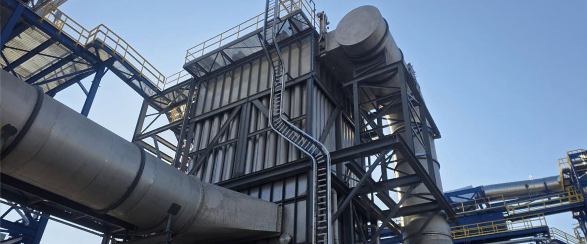
These principles guided NESTEC’s work at SDI Biocarbon Solutions. NESTEC’s scope covered two identical WESP trains — 110,000 ACFM each, 304 stainless steel construction, 544 electrodes per unit — engineered around a highly variable, low-oxygen, pyrolysis-derived off-gas carrying heavy tar and condensable organic loading.
Five lessons from that early commercial installation stand out:
- The gas rarely behaves the way the process flow diagram says it will. On paper, exhaust reduces to temperature, flow rate, particulate loading, and moisture content. In operation, small changes in conditions alter not just gas composition but the physical behavior of condensable organics throughout the downstream system.
- Gas conditioning is part of the process, not part of the emissions equipment. A quench duct upstream of the WESP was required to bring the gas to saturation and keep the inlet below its 300°F design limit. That single decision influenced collection efficiency and reliability more than the collector itself could compensate for afterward.
- Flow distribution deserves engineering rigor. CFD modeling during design established a uniform velocity profile across the WESP inlet, reducing localized high-velocity regions and stagnant zones.
- Tar control and particulate control are one problem. Tars were removed in the WESP before downstream thermal treatment, preventing fouling in downstream ductwork and equipment. Treating them as separate design disciplines is how plants end up with fouled fans and unplanned outages.
- Flexibility matters as much as technical design. NESTEC’s original scope included regenerative thermal oxidizers; when a competing offer changed the downstream flowsheet mid-development, NESTEC adapted rather than forcing the original plan.
Ultimately, the result held. Both WESP trains were installed and commissioned within the project timeline, with gas composition and system performance holding to design expectations.
What This Means If You’re Scaling Biocarbon Now
As more pyrolysis projects move from pilot to commercial scale, the facilities that succeed will be the ones that treat emissions control as a core process design decision. Concretely, that means engineering around actual gas stream chemistry and physical behavior rather than generic VOC or particulate assumptions carried over from combustion.
It also means selecting technologies like WESP, RTO, RCO, or a combination based on what the stream actually requires, and designing for the full range of operating conditions, including startup, upset, and ramp-to-full-production, when tar loading is least predictable. And it means building in flexibility to adapt as project requirements and biocarbon standards mature.
Before locking in equipment, every developer moving from wood pellets into biocarbon should be able to answer questions like: Where will condensation begin in our process, and is that location controlled or incidental? Has the gas been fully characterized for physical state, not just pollutant concentration? Have condensable PM measurements been taken under representative conditions? What happens to the emissions system during startup and upset? How will tar loading change as the facility ramps to full production?
Developers who bring emissions control engineering in early (alongside reactor selection, not after it) consistently avoid the retrofit costs and commissioning delays that come from treating the exhaust stream as an afterthought.
If your organization is evaluating the transition from wood pellet manufacturing into biocarbon or biochar production, contact NESTEC to start a process evaluation for your facility.